ISO 9360-1 Anaesthetic and respiratory equipment –Heat and moisture exchangers (HMEs) for humidifying respired gases in
humans –Part 1: HMEs for use with minimum tidal volumes of 250 ml
Measurement of moisture loss- HME
6.2 Measurement of moisture loss
6.2.1 Principle
The performance of an HME shall be measured by recording the mass of water lost from the test apparatus specified in 6.2.2.
6.2.2 Test apparatus
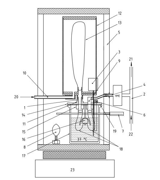
The test apparatus (Figure 1 ) shall comprise the following components.
6.2.2.1 Bidirectional flow generator.
This is a mechanically-driven piston used to produce a flow having sinusoidal waveform.
6.2.2.2 Humidity generator (HG), consisting of
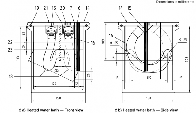
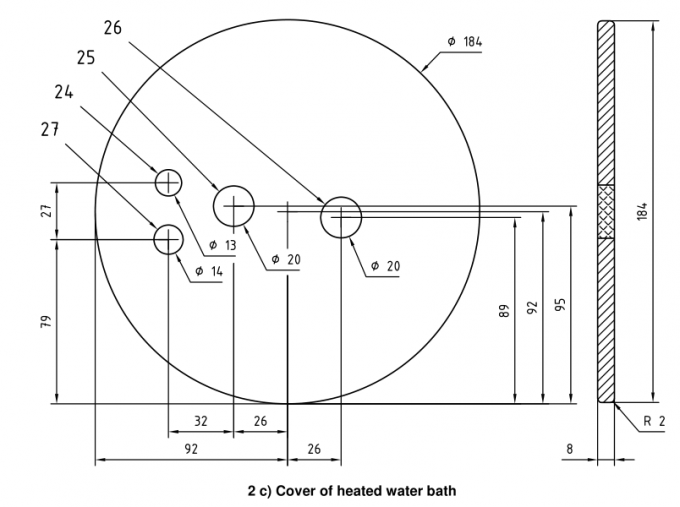
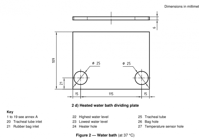
a) a heated water bath (Figure 2) through which air is bubbled in both directions;
b) a rigid cylindrical reservoir (Figure 3) with a maximum volume of 7 l and a diameter of approximately 1 50 mm,containing a 2 l reservoir bag;
c) a thermally insulated chamber (Figure 4), which contains the water bath, the reservoir and a heat source.
6.2.2.3 Air delivery system (Figure 5), consisting of a T-piece with an internal diameter greater than 1 5 mm, and an exhaust tube at least 200 mm in length.
6.2.2.4 Weighing equipment, with an accuracy of ±0,1 g or better in the range of the mass to be measured.
6.2.2.5 Flowrate measuring equipment, with an accuracy of at least 5 % of the reading.
6.2.2.6 Calibration HME (Figure 6) consisting of a housing containing 81 polyvinyl chloride (PVC) tubes arranged in a 9 * 9 array, each with an internal diameter of 2 mm, an external diameter of 4 mm, and a length of 50 mm.
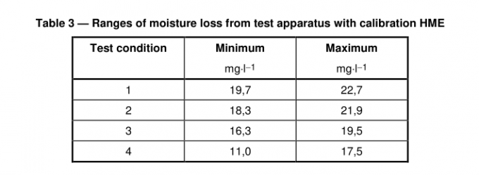
When the apparatus has been constructed and operated as specified in 6.2.2, the moisture loss from the humidity generator with the calibration HME will be as shown in Table 3.
Key
1 to 1 9 see annex A
20 Sinewave generator inlet
21 Air outlet
22 Dry air supply (23 ±1 ) °C, < 1 mg H 2 O per litre air
23 Weighing equipment
Figure 1 — Test apparatus side view6.2.3 Test conditions
6.2.3.1 The air delivered to the HME machine port by the air delivery system shall be at a temperature of 23±1℃ and shall have a humidity not exceeding 1 mg.l -1
6.2.3.2 The HME shall be tested at those conditions specified in Table 2 which are within the range specified for the HME by the manufacturer, at the maximum tidal volume recommended by the manufacturer if this value is greater than 1 l, at a frequency of 1 0 breaths.min -1 , and an I:E ratio of 1 :1 .
6.2.4 Procedure
6.2.4.1 Connect the HG to the bidirectional flow generator.
6.2.4.2 Adjust the bidirectional flow generator to give one of the test conditions in Table 2, measured at the machine port of the HME, within the operating range of the HME as specified by the manufacturer. Adjust the flowrate of air delivered by the air delivery system to be between >1 and <1 ,5 times the peak flowrate of air drawn into the machine port of the HME. The peak flowrate is stated in Table 2.
6.2.4.3 Operate the test apparatus with an HME of the same type that is to be tested for a minimum of 1 h,with the water bath at a temperature of 37 ±0.5℃ , and the air within the insulated chamber at temperature of 37 ±1℃ . Maintain this temperature for the duration of the test procedure.
6.2.4.4 Confirm that the volume of air leaving the machine port of the HME is that required for the test condition chosen from Table 2.
6.2.4.5 Record the mass of the HG only (i.e. not including the HME) (m 0 ).
6.2.4.6 Replace the HME with the one to be tested and operate the test apparatus for (60 ? 5) min.
6.2.4.7 Record the mass of the HG only (i.e. not including the HME) (m 1 ).
6.2.4.8 Continue to operate the test apparatus up to the maximum time of use recommended by the
manufacturer.
6.2.4.9 Record the mass of the HG only (i.e. not including the HME) (m 2 ).
6.2.4.10 Confirm that the volume of air leaving the machine port of the HME is that required for the test condition chosen from Table 2.

6.2.4.11 Calculate the HME moisture loss for the first hour, M 1 , using the formula
M 1 = (m 0 -m 1 ) /V 1
where
m 0 is the initial mass of the HG;
m 1 is the mass of the HG after 1 h;
V 1 is the total volume of air leaving the HME machine port during the first hour of the test.
6.2.4.12 Calculate the HME moisture loss for the entire duration, M max , using the formula
M max = (m 0 - m 2 ) /V 2
where
m 0 is the initial mass of the HG;
m 2 is the mass of the HG after the maximum time of use as recommended by the manufacturer;
V 2 is the total volume of air leaving the HME machine port during the entire test period.
6.2.4.13 Repeat the procedures in 6.2.4.2 to 6.2.4.1 2 for all the test conditions given in Table 2 which are within
the operating range of the HME as specified by the manufacturer.
When the apparatus has been constructed and operated as specified in 6.2.4, the moisture loss from the humidity generator with the calibration HME attached should be as shown in Table 3. This shall be confirmed for the specific test apparatus by conditioning the test apparatus for at least 2 h (see 6.2.4.3), and then operating the test apparatus for a period of 2 h with the calibration HME, and measuring the mass loss over that period (all mass measurements shall be made without the HME attached to the test apparatus).
