ISO 23328-1 Breathing system filters for anaesthetic and respiratory use —Part 1: Salt test method to assess filtration performance
Annex A
Conditioning of BSF
A.1 Principle
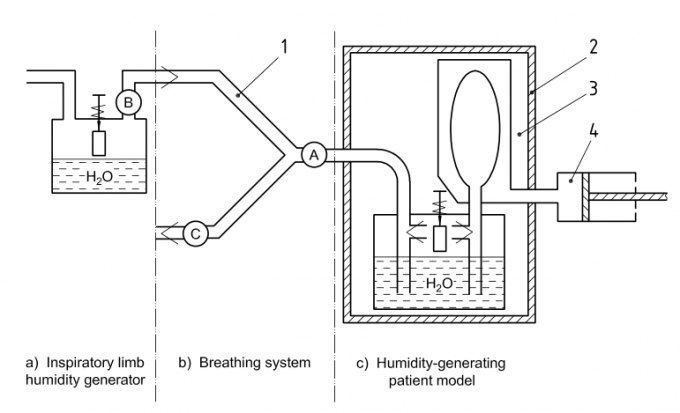
BSF are exposed to humidified air in a conditioning apparatus to simulate a period of clinical use before they are tested for filtration efficiency. The conditioning apparatus consists of a humidity-generating patient model connected to a breathing system with or without an inspiratory limb humidity generator. The BSF can be positioned at various points in the breathing system, to simulate clinical use or as recommended by the manufacturer.
A.2 Test conditions
The ambient conditions during the conditioning shall be:
temperature: (23 ± 2) °C;
relative humidity: (60 ± 15) % RH;
pressure: (96 ± 10) kPa.
A.3 Apparatus
A.3.1 Inspiratory limb humidity generator [see Figure A.1 a)], to increase the temperature and relative humidity of the inspired air if required (see A.4).
A.3.2 Breathing system [see Figure A.1 b)], consisting of an inspiratory limb, a Y-piece with a patient connection port, and an expiratory limb, having one-way valves placed at the ends of the breathing system limbs to ensure unidirectional flow through the breathing system.
A.3.3 Humidity-generating patient model [see Figure A.1 c)].
The model shall consist of the following:
a) an insulated chamber, the internal temperature of which is maintained at (37 ± 1) °C;
b) a heated water bath, maintained at (37 ± 1) °C, through which air is bubbled in both directions;
c) a rigid reservoir containing a 2 l reservoir bag;
d) a reciprocating piston/bellows pump.
A.4 Positioning of BSF
A.4.1 General
The positioning of BSF for conditioning shall be as shown in Figure A.1 and as described in A.4.2 and A.4.3
A.4.2 With the inspiratory limb humidity generator in place in the breathing system
A.4.2.1 To simulate use in a circle breathing system with a carbon dioxide absorber, set the mean temperature at the inlet to the Y-piece to (26 ± 1) °C and the relative humidity to > 90 % RH and place the BSF at position A.
A.4.2.2 To simulate use with a hot water humidifier, set the mean temperature at the inlet to the Y-piece to (38 ± 1) °C and the relative humidity to > 90 % RH and place the BSF at position B.
A.4.3 With the inspiratory limb humidity generator removed from the breathing system
A.4.3.1 To simulate use in a non-rebreathing system, place the BSF at position A.
A.4.3.2 To simulate use in the expiratory limb of a breathing system, place the BSF at position C.
A.5 Procedure
A.5.1 Set up the apparatus and operate the humidity-generating patient model, ensuring that the water bath temperature has stabilized at (37 ± 1) °C. For the conditioning requirements specified in A.4.2, operate the inspiratory limb humidity generator until the temperature and humidity measured at position 1 of Figure A.1 have reached the specified values. Set the patient model parameters according to the intended use of the
BSF, as given in Table A.1.
A.5.2 Fit the BSF in the breathing system at the position required to simulate its intended use, as given in A.4 and Figure A.1.
A.5.3 Operate the apparatus to condition the BSF for the maximum period recommended by the manufacturer for clinical use, or for (25 ± 1) h if this is not stated.
A.5.4 Within 5 min of the end of the conditioning period, remove the conditioned BSF and test the BSF in accordance with Clause 3
Table A.1 — Patient model parameters for conditioning BSKey


1 position of temperature and humidity sensor for use with inspiratory limb humidity generator
2 insulated enclosure
3 rigid reservoir
4 pump
A, B, C Positions of BSF for testing (see A.4)
NOTE Symbols are in accordance with ISO 8835-2.
Figure A.1 — Conditioning apparatus for BSF

